Flowmeters on fire trucks have been around for a few decades now - some folks like them - some folks don't. To many folks, a flowmeter is a "mystical" device that somehow converts flow into a digital readout. We thought we would share a few photos of a replacement flowmeter being installed so that everyone can see what the moving parts look like. Basically, most flowmeters used on FD pumpers use the "paddle-wheel" design and are inserted in a straight section of pipe on the appropriate discharge.
Water passes through the pipe, spins the small paddle wheel that is inserted into the stream, and then the mechanical signal is converted to an electrical signal that results in a digital display on a panel somewhere remote from where the paddle is physically located.
Two key items about flowmeters are...
1. The meter must be calibrated for the size of pipe.
2. The meter must be calibrated for the flow - generally done using a fixed orifice and pitot tube.
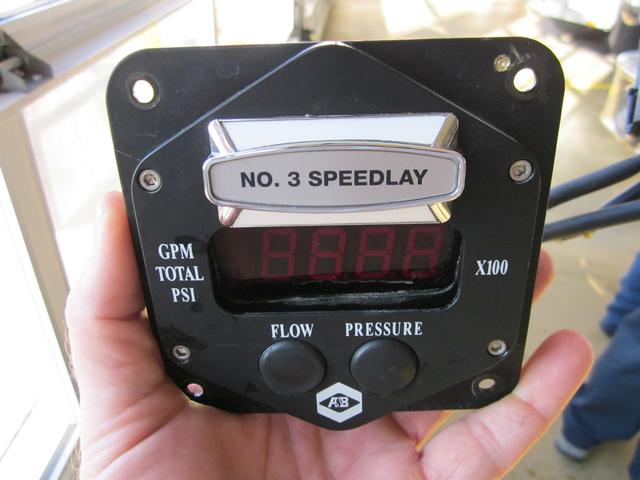
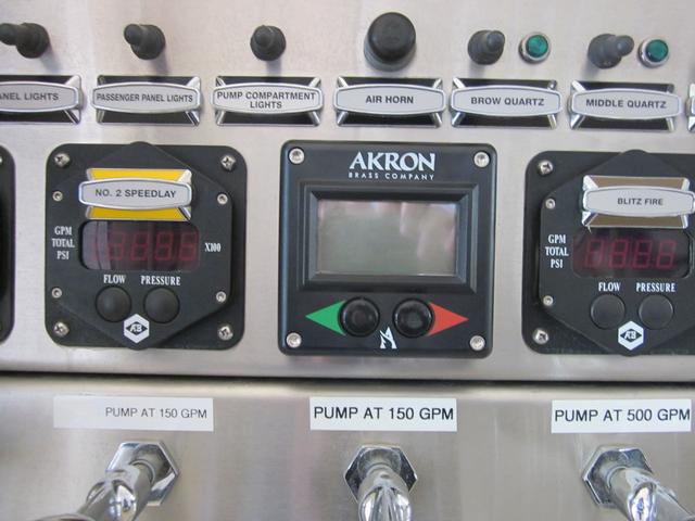
This is the display module of a new, Akron flow meter.
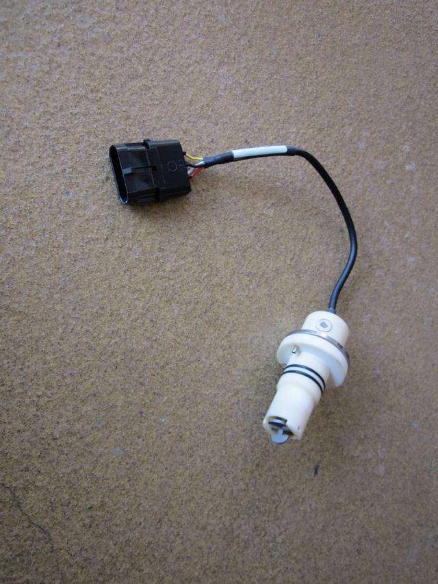
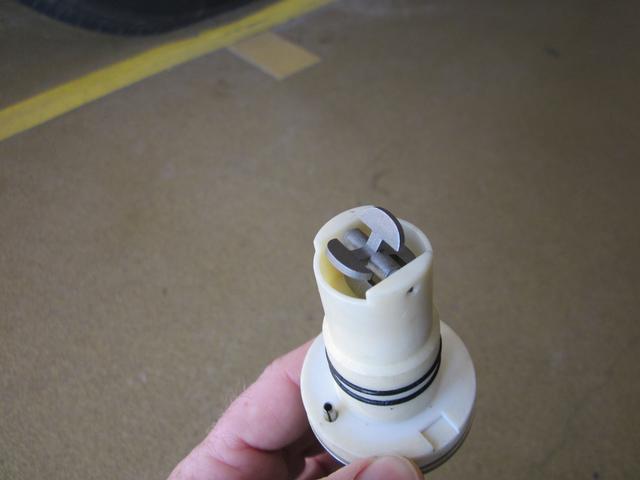
The mechanical part of the flowmeter is a rather simple, paddewheel device.
Water passing through the discharge pipe comes in contact with the paddlewheel causing it to spin and generate a digital readout on the display module.
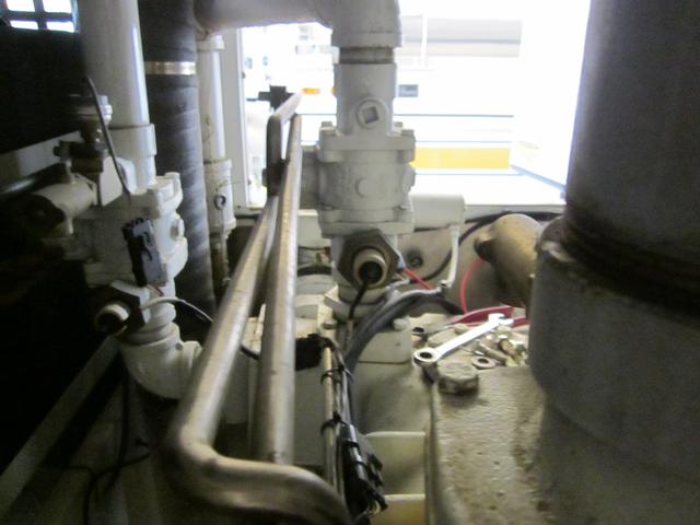
The paddlewheel component fits into the pipe somewhere along a straight run of the pipe - this can be hard to find in a pump compartment.
Digital readout flowmeters are used on many FD pumpers as the means by which the pump operator establishes the proper flows for the hoselines being pumped.